


Kitty Cat Electrical Tests
The following Kitty Cat electrical tests and troubleshooting procedures are reprinted from an Arctic Cat service manual and are extremely helpful if you believe your snowmobile has an electrical failure.
These electrical tests are valid for post 1985 Suzuki engines with the headlight and taillight assembly. Eelctrical questions should be posted in our Kitty Cat forum.
The following information and procedures are copyright Arctic Cat or Artco, depending on the era they were written...
Jump to: Wiring Harness | Ignition Coil | Charging Coil | Secondary Coil | Primary Coil | Lighting Coil | Check and Set Timing
Testing the Kitty Cat Ignition System
The ignition system used in the Kitty Cat (Kokusan) is the open circuit type. It is opposite from other ignitions used on all the larger Arctic models (naturally close type) and this must be kept in mind when selecting your troubleshooting method.
Before starting the troubleshooting procedure, you must first pinpoint the problem of an engine which won't start, to either the electrical system, fuel system, or the engine inner components.
To accomplish this, first remove the spark plug and inspect its condition. If questionable, replace it with a new one. Adjust the spark plug gap to 0.5 - 0.7 mm or 0.020 - 0.028.
Ground the spark plug to a good clean surface, turn on the switch and crank the engine over hard using the recoil. As the engine is being cranked over, observe the firing tip of the spark plug.
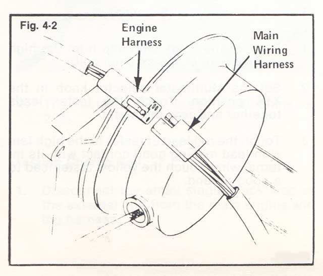
If no spark is present, disconnect the main engine wiring harness and repeat the test. If there is now spark present, with the main harness disconnected, the problem lies in the safety switch or the wiring harness.
If no spark is present, the problem is in the ignition system. To troubleshoot these components, the following procedure is recommended.
NOTE: To test the ignition system, use either an ohmmeter or CDI tester.
Wiring Harness Test Procedure
- Disconnect the wiring harness at the engine.
- Perform test at the main harness four prong connector. Connect one ohmmeter lead to the black wire in the connector. Attach the red ohmmeter lead to the brown wire in the connector.
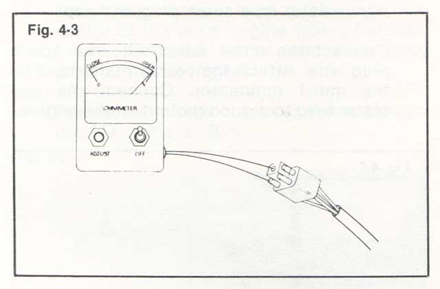
- With both the ignition and safety switch in the "ON" position, the meter must register "OPEN". If the tester reads "CLOSED", disconnect the ignition switch from the main wiring harness. If the tester now reads "OPEN", replace the ignition switch.
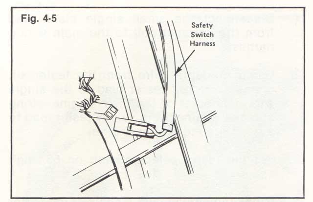
- If the meter remains in the "CLOSED" position with the ignition switch disconnected, disconnect the safety switch. If the meter now reads "OPEN", replace the safety switch.
- If the meter remains in the "CLOSED" position with both switches disconnected, replace the wiring harness.
Ignition Coil Output Test
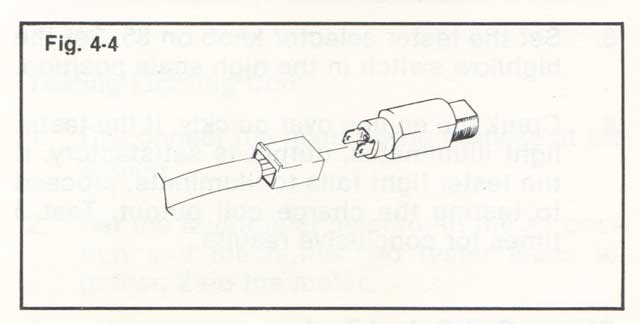
- Remove the resistor spark plug and spark plug cap from the engine. Next, install a non-resistor type spark plug and cap.
- Connect the mm-1 adapter to the spark plug wire. Attach the yellow tester lead to the mm-1 connector. Connect the red tester lead to a good ground on the engine.
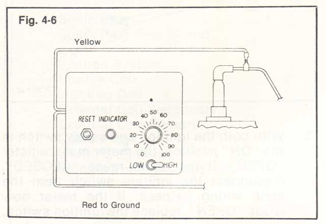
- Set the tester selector knob on 85. Set the high/low switch in the high scale position.
- Crank the engine over quickly. If the tester light illuminates, output is satisfactory. If the tester light fails to illuminate, proceed to testing the charge coil output. Test 3 times for conclusive results.
Charge Coil Output Test
The new Kitty Cat ignition has incorporated the CDI unit and external coil into one component. Because of this, we will proceed directly to the charge coil test after testing the external coil output.
- Disconnect the small single black lead from the external coil to the main wiring harness.
- Using a adapter wire from the tester kit, connect the red tester lead to the single wire connector of the main engine wiring harness. Connect the yellow tester lead to a good ground on the engine.
- Set the tester selector knob on 55, high scale.
- Crank the engine over quickly. If the tester light illuminates, output is satisfactory and this would pinpoint the external coil and CDI unit as being defective.
- If the tester light fails to illuminate during the charge coil test, replace the charge coil. Repeat the test 3 times for conclusive results. Push the reset button between each test.
NOTE: Before replacing any ignition components make sure none of the connectors are corroded or loose.
Testing Electrical Resistances
NOTE: All resistance tests on the Kitty Cat ignition can be made using the Arctic Multitester (pin 0144-053). The following test procedure starts by testing the resistance of the spark-plug cap and working back to the charge coil under the flywheel. Replace any component that does not have a test value within specification given.
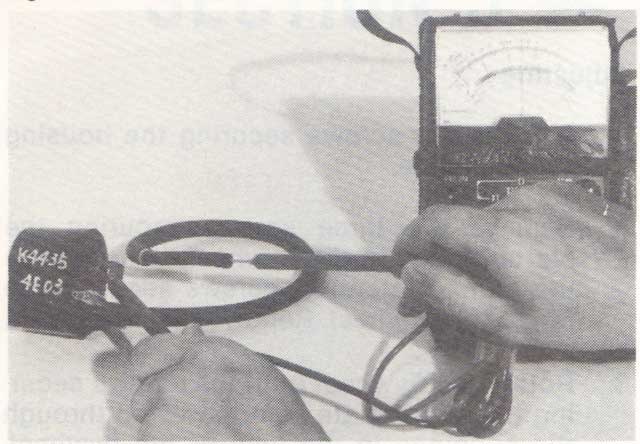
Testing the Spark-Plug Cap
- Remove the spark-plug cap from the high tension lead by rotating counterclockwise.
- Set the Multitester selector knob on the X1K position. Touch the tester leads together and zero the meter.
- Touch the two tester leads to either end of the spark-plug cap, making good contact with its metal contacts.
- Spark-plug cap resistance must measure 5000 ohms +/- 20%.
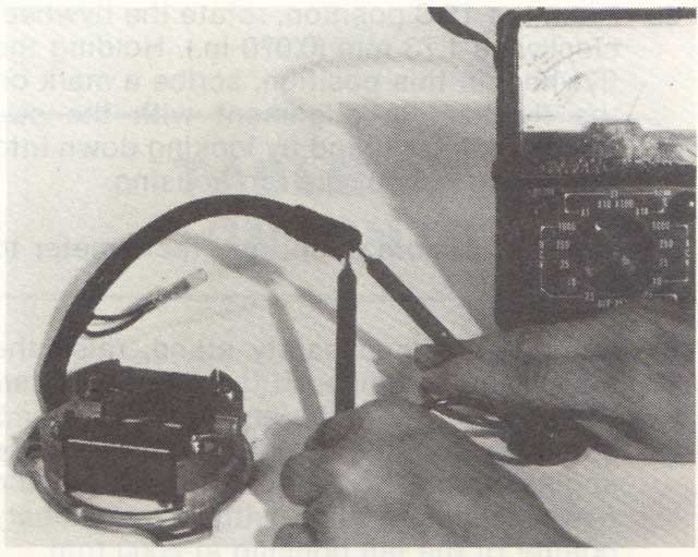
Testing External Coil Secondary
- Remove the spark-plug cap from the high tension wire of the external coil.
- Set the Multitester selector knob in the X1K position. Touch the tester leads together and zero the meter.
- Touch the red lead of tester to the high tension lead making good contact with its internal wire. Touch the yellow tester lead to a good ground.
- Secondary resistance must measure 5900 ohms +/- 20%.
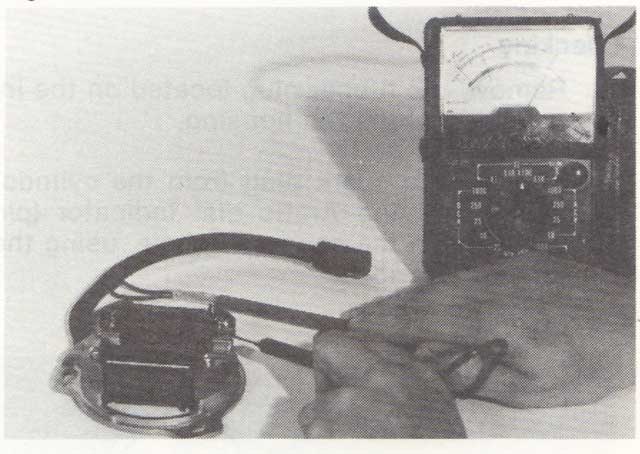
Testing External Coil Primary
- Disconnect the single external coil lead from the main wiring harness.
- Set the Multitester selector in the X1K position. Touch the two tester leads together and zero the meter.
- Touch the red tester lead to the single black lead of the external coil. Touch the black tester lead to the metal center post of the coil.

- The meter should read 11,000 ohms +/- 20%.
Testing Charge Coil
- Disconnect the small single black lead of the external coil from the main engine wiring harness.
- Set the Multitester selector knob in the X100 position. Touch the tester leads together and zero the meter.
- Touch the red tester lead to the single connector of the main engine wiring harness. Touch the black tester lead to a good ground on the engine.
- Resistance of the charge coil must measure 117 ohms +/- 20%.
Testing the Lighting Coil
- Disconnect the main wiring harness at the engine.
- Set the Multitester selector in the X1 position and touch the two tester leads together. Zero the meter.
- Touch the two testers leads to the two yellow wires in the engine wiring harness connector.
- Lighting coil resistance must measure 1.3 ohm +/- 20%.
Checking the Kitty Cat Timing
NOTE: Engine timing can only be checked with the engine running at 6000 rpm, using a good quality timing-light. Before checking the timing, allow the engine to run and warm-up for 5 min.
How to Check the Timing
- Remove the rubber plug located on the intake side of the fan housing.
- Remove the spark plug from the cylinder and install the Arctic dial indicator (p/n 0144-009) in the spark plug hole, using the adapter provided.
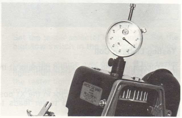
- Rotate the engine to top dead center (TDC). Set the dial of the indicator to the zero position and rotate the flywheel back and forth to check accuracy of zero position. Needle must change direction exactly at zero on dial.
- From the TDC position, rotate the flywheel clockwise 1.73 mm (0.070 in.). Holding the flywheel in this position, scribe a mark on the flywheel in alignment with the stationary pointer found by looking down into the timing hole of the fan housing.
- Connect a timing light and tachometer to the engine.
- Using a shielded safety stand, raise the rear of the machine off the floor and start the engine. Allow the engine to run for 5 min. at a fast idle. Gradually increase the engine rpm, the scribed mark on the flywheel should align with the stationary pointer of the fan housing at 6000 rpm.
- If the timing is not correct, adjust timing.
Adjusting Kitty Cat Timing
- Remove the screws securing the housing to the engine.
- Remove the three screws securing the starter pulley to the flywheel; then remove the four countersunk screws securing the fan to the flywheel. Remove pulley and fan.
- Rotate the flywheel until the screws securing the stator plate can be viewed through the openings in the face of the flywheel.
Using a long screwdriver, loosen the three screws and rotate the stator clockwise or counterclockwise to correct timing. Tighten screws, reassemble engine and recheck timing for accuracy.
NOTE: The Kitty Cat engine runs counter-clockwise so to advance timing, rotate the stator plate clockwise. To retard timing, rotate the stator plate counterclockwise.
See also: 72 Carburetor Parts | 72 Crankcase and Cylinder Parts | 72 Cylinder Cover Parts | 72 Magneto Parts | 72 Piston and Crankshaft Parts | 72 Recoil Parts
Latest from KCS...
There's no time like the present to track down parts, restore, and rebuild your snow machine, even the big boys need their sleds to be trail worthy.
We also offer easy access to snowmahine parts for all the manufacturers including Polaris, Skidoo, and Yamaha snowmobiles.
There's also brand name boots, gloves, jackets,
,
and
and more snow riding stuff available from our sponsors.
Elsewhere in Snowmobiling...
- Upcoming Snow Shows... There are quite a few, even in the warmer months Snowmobile Shows scheduled for this year. Vintage snowmobiling is alive and well, check for an event near you...
- Restoring a Vintage Polaris? There's plenty of Vintage Polaris restorations to check out, also they specialize in "old-school" Polaris sled parts...
- Calling Wisconsin Snowmobiliers! Wisconsin Clubs Wisconsin offers the finest snowmobile trail systems in the country, these trails are maintained by volunteers who are members of the local snowmobile clubs. Join a club today...
- It's not "snow time" yet... National Snowstorm Forecast Keep watching the weather and stay tuned for the Farmer's Almanac and the snowfall prediction for the winter of 2023/2024.